


PRODUCT
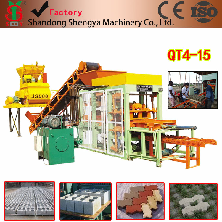
Maim Technical Specifications:
| Technical | Parameters | ||
| Overall Size | 3700×1500×2600mm | ||
| Cycle | 15-18s | ||
| Pallet Size | 900×550×30mm | ||
| Power | 29.4kw | ||
| vibration force | Max 50KN | ||
| rated pressure | 16Mpa |
Production Capacity
| SIZE(L*W*H) | pcs/drop | pcs/hr | pcs/shift |
| 400X200X200mm | 4 | 600-960 | 4800-7680 |
| 400X150 X200mm | 6 | 900-1440 | 7200-11520 |
| 400X100 X200mm | 8 | 1200-1920 | 9600-15360 |
| 400X250X200mm | 3 | 450-720 | 3600-5760 |
| Paver:200X100 X60mm | 16 | 1920 | 15360 |
| Paver:200X163 X60mm | 8 | 1200 | 9600 |
QT4-15 Operating Instruction
Contents
一、Safety rules of operation
二、Application and characteristics
1. Storage hopper and the supply hopper are set up separately and quantitative feed2. Compulsory Feeding Equipment
3. Excellent Vibrating System
4. Intelligent Control
5. Efficient Work Surface
6. Multifunction
7. Main specifications
三、Structure Instruction
1. Machinery installation, Debugging and maintenance(1)Installation
(2)Debugging
(3)The installation and adjustment of the mould(4)The using and maintenance of the machine(5)Electric Control
2. Hydraulic system
(1)Matters need attention before or after oil pump starting.
(2)Hydraulic system usage and maintenance(3)Common errors and Exclude measures of the hydraulic system一、Safety rules of operation
1. The operators and examiners should learn this instruction carefully.
2. Make sure to cut off the power before adjusting, filling oil, clearing, examining the machine.
3. Please put something between the die head (upper mould) and the mould box (under mould) to support, when you clear the mould, examine and fix the mould. To avoid the die head fall down, that may damage the mould and cause accident!
4. After all the parts of the machine are adjusted well, you should install all the protecting nets, and make sure there are not any tools and fittings are left on the machine. Put all the tools in the toolbox after using.
5. After everything is ready and make sure there is nothing wrong, you can connect to power supply, operate the machine carefully, Non-staff must be away from the machine.
6. Before operation, you much check whether the moving parts in the initial state, especially the discharging system is ready for feeding, pallet supply system have already convey the pallet to the working vibrating table.
7. Close the electrical box door, you can start the machine.
8. When machine stop working, you mush turn off all the switches, make sure they are in “power off” or “stop” position.
9. All workers must comply with safety regulations.
二、Application and characteristics
1. Make the Storage hopper and the supply hopper separate and quantitative feedTraditional block shaping machine, the storage hopper and supply hopper are the same one, they are close to the vibrator, will be influenced by the vibrating, make parts concrete liquefied quickly, extended feeding time and increased difficulty of feeding. QT4-15 Block shaping machine make the storage hopper and supply hopper separately, Storage hopper (about 500 liters) is far away from the local oscillator and we have isolation measures too, we use closed type belt convey the Quantitative raw materials to the hopper, and there is Quantitative hopper switch which can control the top thread of the hopper(the raw material can be adjusted).
2. Compulsory Feeding Equipment:
Because the rib thickness of the blocks is too thin(usually 13-16mm), traditional feeding way can not feed materials into the molding box evenly. QT4-18 block making machine adopts compulsory feeding system(there are many ranks of mixing forks in the distributed box), when distributed box deliver to the top of molding box, mixing forks swing to feeding materials into the molding box compulsively, both guarantee the feeding speed as well as the even feed of the whole molding box.
3. Excellent Vibrating System:
The main vibrating system of QT4-15 block making machine is frequency conversion amplitude modulation vibrating system (frequency conversion amplitude modulation can change belt pulley) , made up of vibrating motor and vibrating box, besides, the pressure head is equipped with the vertical orientation vibrator, can form complex vibrations. When the block making machine is working, demoulding tank is locked tightly to the vibrating table, shape the phenomenon of table and mould vibrate together, and also the main vibrating system can do frequency conversion amplitude modulation vibrations, not only can guarantee the shaping of different performances of materials , but also make different specifications of products dense sufficiently, so it has very high efficiency and very small consumption.
4. Intelligent Control
Affected by the materials’ dryness and humidity, aggregate’s change, the materials of concrete is different after mixed, under the premise of making sure the quality, set up the optimum forming parameters and the best conservative forming parameters of the products, higher than the upper limit, reduce feed automatically, lower than lower limit, feed automatically, besides this machine also have the functions of displaying real-time dynamic mechanical action, checking faults automatically, showing input, outputting faults locations.
5.Efficient Work Surface
Because adopt the vibrating new technology when designed to make the efficient vibrating forming area can up to 0.5m2(850×550mm), provide the foundation for concrete bricks forms scale production.
6. Multifunction
一、Pieces of every mould: 390×190×190mm 4pcs/ mould二、Pallet size: 850×550×35mm (wooden)三、Molding cycle: 15-20 s (depends on the brick specification and materials)四、Vibrating frequency: 70HZ (Max)
五、Vibration force: 50KN (Max, adjustable)六、Total power: 29.4kw
七、Overall dimensions: 3700×1600×2500 mmStructure Instruction
Structure of QT4-15 Fully-automatic Hydraulic Block Making Machine一、Vibrating system: composed of motor, vibrating table, vibrating box, vibrating rubber and springs etc.
Two sets opposite direction, interactional motors drive a couple of interoperable off-center gear shaft to vibrate in the vibrating box through belt, so that can make vibrating box vibrate vertically and orientedly,, this kind of vibration mode can make sure vibrating box have even amplitude of vibrations, bricks have good denseness.
二、Slider guide rod system: made up of molding box slider, pressure head slider, guide rod snubber mat and synchronizer etc.
Molding box is fixed on the molding box’s slider, demoulding cylinder binds molding slider to make molding box press on the vibrating table slightly when vibrate and form to get a much more strong vibration efficiency. When change moulds, adjust height bolts that installed on the pressure head slider can solve the problem of brick’s height.
三、Demoulding system: made up of demoulding beam, demoulding cylinder and synchronizer etc.
Up and down of the molding box’s realization is controlled automatically by two parallel connection demoulding cylinder, synchronizer realizes molding box’s left and right synchronization to make its up and down automatically.
四、Mould: through changing moulds, this machine can produce different kinds of bricks , molding box usually adopts fabricated mode, when damaged mold core, clapboard and scaleboard are wore to a certain extent, can be changed by new of them, do like is this not only very convenient for maintenance, but also can save user’s mould expenses largely.
五:Compacting System: It is composed by the association board, the transition linking block, the die vibrator and the die cylinder’s synchronizer.
When producing blocks, you should discharge the transition linking block and make die cylinder hinged altar connect with association board directly, so that the up and down of mould head can be controlled by two shunt-wound die cylinders.
六:Material Distribution System: it is composed by material distribution platform, arch-breaking devices, material distribution carrier and auxiliary hopper.
The mixed material in auxiliary hopper is supplied by conveyor ( it can be controlled by material level meter according to actual needs). Forward feeding and backward of material distribution carrier is controlled by distribution cylinder fixed up to the material distribution platform.
七:Feeder system: It is composed by gear, belt machine, storage hopper. Its function is storage of mixed material and feeding auxiliary hopper.
八:Pallet supply system: it is composed by the track, pallet supplying trolley, pallet supplying cylinder and pallet’s warehouse. Pallet supplying cylinder lead pallet supplying carrier forward feeding or backward. The finished block with pallet is put out the vibration platform by next pallet.
Machinery installation and commissioning and maintenanceThe machines can be installed according to installation plans. (see attachment). The embedded parts should be installed firmly; infrastructure should meet the design requirements, and have enough strength to install.
After arriving at the customer’s production sites, machine should be made series of safety checks due to lifting and transportation1.Check whether there is a lack of machinery parts2.Check whether the machines are damaged or deformed during lifting transport3.check whether there is any loosening of fasteners of the main parts of the machine4.People should have a comprehensive clean to machines, with particular attention to the mold box, material distribution carrier, belt machines, and storage hopper. It can prevent the hardening concrete mixture from damaging the machine一:Machinery installation
According to relevant regulation the machines out of factory have been test in factory and the relative position of all the parts have been adjusted, fixed. The hydraulic station circuit, electric operator are been discharged in order to facilitate the transport, but belt conveyor and block conveyor is independent relatively.
Due to above reasons, the main job of the installation is position the host machine correctly and restoring the respective mutual relations disrupted by transport.
Installation of Host machine should make its axis coincidence with the basis axis. The spirit level measured the slider guide’s verticality. If it is not vertical, the steel plates can be added between end of the foot of machine and embedded parts to be adjusted verticality to meet the vertical requirements. And then the welding machine can be used to weld the end of foot plate embedded parts with Spot 1-2, but not full welding.
After the host position, hydraulic station, control of distribution cabinet are positioned in accordance with the relative position between them and the host machine. And in accordance with relationship the connection of circuit, line between the hydraulic station and the host machine, and power distribution cabinet are restored. Block conveyer generally not fixed. Height of transmission V belt should be same with host machine vibratory table.
After finishing the above work, please check whether the electric access is connected correctly in accordance with the requirements and connect water into and out access of hydraulic station cooler.
After installation, please conduct a comprehensive inspection to check whether there are key parts of fastener loosening, and whether there is any foreign items resistance, and to add fuel to hydraulic moving parts, the relative sliding parts before testing.
二.Machinery commissioning
After machines are installed, machines can be tested. First of all, machines are connected to the main power supply, then are operated manually in order to see whether machines run coordinately, the actions come to accuracy place and whether there is hysteresis, and friction or collision. It is also checked whether joints of oil circuit have Oil permeability. After confirming all parts run well, machines are operated by hand to trial production. The machine can be run coordinately through adjusting limit control switch. By adjusting height of bolts on the pressure head slider controls degree of high degree of block in the scope of permissible error. Hopper can adjust dosage level meter according to concrete needs of every mould in order to meet fully the needs of every mould. The trial production should be 10 pallets to 20 pallets. After testing, Spot welding should be welding fully, and then machines can be transferred to automatic control of production.
三.The installation and adjustment of mouldsThe mould that is as free attachment is normally 240*115*53mm,the standard mould. And the height of mould box is 135mm ,the height of the head mould is 390mm(the total height together with contact part).the distant of the down surface of two ends board on the mould box to the bottom of mould box should be 117mm.
When you need to change the mould, you should do some adjustment with machine. For example, take the mould of eight holes brick as example, the step is as follows:
A .put the mould in the machine down, you should remember the installation of the contact parts before doing that.
B .lift the mould connect board up, then put the new mould box on to the mould slipping board ,and put a mat on the mould box ,and then make the mould head connect board down ,connect the mould head with the mould head connect board ,then put away the mat ,then make the mould head into the mould box freely ,and finally fix the mould head tightly .
C .after the fixing mould, you should make the working platform down by 5mm because the mould box is lower than usual ones.
D .the limit screw in the mould head should be change 25 mmE .adjust the limit switch of the mould slipping boardF .adjustment by hand operation when not using the concrete material, to confirm if the adjustment is accurate.
H .try starting the machine after feeding material ,note if the mould box can lift up in lever when the mould off .be sure that the foursquare of bricks are all same height .be sure that there is need to adjust the bolt or the limit switch .make the material place device .finally fix any part need to fix tightly.
If you need to install the mould 390*190*190mm standard block mould, besides the experiment adjustment above, you should put away the mould connecting partThe using and conservation of the machine1.Confirm if all parts are there before operation. If the belt is tight, and the connecting line is down, if the line is connected with ground.
2.Confirm if the all connect of oil way is right and if the airproof ring is added.
3.Check if the connecting screw of the vibrating board is tight4.Be sure that there is lubricating oil in the right part5. Forbid vibrator works no using raw material6.After everyday ‘s work, you should make any system of machine in the original ,and clear any concrete material, never using mater7.You should change the lubricating oil usually of the vibrator and reducer device8. Prevent wet and solarization for the electric controller ,and never damage the touch screen9.Check the dimension of wood pallets, never use them that are bad .
10. If some parts wear out, you should change in time ,in case it will damage the machine四. Electric controlling
(一)the manner of controlling
QT4-15 model is controlled by PLC program ,you can operate the machine by the button or using the man-machine interface screen, the controller is made up of manual and automatic .it works when single cycle and continual .
1. Manual controlling: you can operate this machine by the operating surface button, this manner is used generally for urgent thing and when our technicians installation2、Auto-control:Single cycling control and continuous controlA: Single cycling control: Machine’s movement parts are all on the automatic state(initial position) push the button of auto-start then can produce full mould blocks and delivery to blockConveyor: The machine will automatically stop in the initial position. In this way for the test mode to view the situation of the need for forming a single block production and downtimeB, continuous control: As long as there are sufficient materials in the storage hopper and there are enough pallets in store, push auto-start button, the machine will be able to work this way for normal production.
(二) initial position
1, pallet supply installations in the former position (manual for the board to the vibration platform)2, discharging system in the back place ( there are material in hopper )3, pusher head at up level
4, mould case at the down level
5, feed conveyor belt and delivery machine are in standstill(三) action procedures
1, Pallet supply device reset backwards, discharging system feed forward;2, End feeding, discharging system back down reset die compaction mold box up and down the aggregate at the same time vibration, arrived at the designated height (to a higher degree of block) to stop vibration demoulding delay;3, Mold me up demoulding supreme place;
4, Mould head upward, pallet supply device forward (or delay forward) for board and forming a final block to the block, together with the pallet on the conveyor;5, Mould case down to wooden pallets on the vibration table;6, Repeat action cycle by the above procedure.
(四) human-machine interface
This man-machine interface is with the SWD-C-type touch screen, it is mainly used by manual operation, the parameters set up automatic monitoring and fault description of the phenomenon and to exclude.
5, Electrical system maintenance, the system uses the PLC control, so simple structure, easy maintenance, according to electrical schematics, PLC reference to the output, input instructions to determine where the fault.
The hydraulic system is designed according to QT4-15-type molding machine features, through a simple procedure to adjust. Can easily modify the parameters of vibration system to regulate the fuel tank’s speed, able to adapt to different type of aggregate block the production of features, the system can better ensure the smooth implementation of parts moves quickly to control more accurate and reliable, particularly suitable for thin-walled brick production.
Operation and maintenance personnel must carefully read the prospectus to understand the whole principle of the hydraulic system, can ensure proper maintenance of normal use the hydraulic system.
一、Notes of before and after pump start
1, plus full tank of hydraulic oil, oil level should be above the thermometer scale, hydraulic oil is about 400kg, the viscosity of the oil temperature under work should be appropriate, N46 # anti-wear hydraulic oil is supposed to be used ;2, hand-rotating motor shaft in order to check the motor shaft and pump shaft’s connection is in same center or not , whether rotation is smoothly or should be re-adjusted3, before starting pump , check the pump rotation is correct or not, when formal launch, to be taken continuous to move three times to make a gradual increase in pump speed to ensure adequate lubrication;4, the new pump or the pump does not work long-term, in the initial stage of operation should be under the pressure of 0.98MPa low-voltage operation, in order to ensure pump adequate lubrication, and then slowly adjusted to the work pressure and the work pressure pumps : 3MPa, 7MPa, 14MPa .
5, Pay attention to oil temperature, if the oil temperature under 10 ℃ it should be heated first, until the temperature reaches 15 ℃ then it can be carried out at full capacity.
一、, the use and maintenance of the hydraulic systemIn normal condition, hydraulic system can work stably and has fewer malfunctions, but if it is operated or maintained wrongly, it will be very easy to bring out all kings of faults. Now some special warnings that people should know during use and maintaining are stated as below:
1、Keep the cleaness of hydraulic oil and its surfaceFacts prove: all kinds of malfunctions and damages of hydraulic system have much relationship with below reasons: hydraulic oil goes bad, is contaminated or can’t be sealed well. Both of two aspects can influence each other.
A、Hydraulic oil in the oil box should be keep on the normal level. People must observe oil indicator and make up hydraulic oil to keep normal oil surface.
B、Hydraulic oil must be filtrated strictly. Our system has rough oil filter on the oil-absorbing inlet, has extractive oil filter on oil-returning inlet. The oil filter must be checked out often, once damage or stem is found, it is needed to renew. When people add oil into oil box, the oil is needed to pass 120 mesh filter screen.
C、Hydraulic oil should be checked out often and renewed periodically. It is suggested that when new machine work for 50 hours, the whole hydraulic system should be cleaned out completely.
D、The elements of hydraulic system can’t be taken down at will. When people take down elements, firstly the pressure of hydraulic system should be discharged. After elements are taken down, they should be clean out and people need to change sealing ring. When elements are re-installed, metal objects are avoided to fall into them.
2、Prevent temperature of hydraulic oil is too highThe working temperature of hydraulic system is between 30℃—80℃. Around 50℃ is the best temperature for working. When machine is working, temperature of hydraulic oil can't exceed 80℃, a few warnings during using are as below:
A、Keep enough oil level of oil box, keep enough oil to circle and cool in the system.
B、Keep enough water in cooler, pipe line work freely. Take care that it is needed to add purified freshwater into cooler. In cold season, when the machine is stopped to use, the left water in cooler should be let out. About half a year, the cooler should be cleaned out for one time.
C、When the hydraulic system doesn’t work, oip pump must be taken down.
D、According to the requirements of instructions to choose right hydraulic oil3、Daily and regular check of Hydraulic systemSometimes many large malfunctions of hydraulic system are caused by small abnormal phenomenon. But enough daily and regular maintenance and check can find and avoid some potential malfunctions.
1、People should abide by operation rules and requirements of using and maintenance.
2、Take care to check sound of oil pump’s working. If sound is too strong or abnormal, it is needed to check the reason and remove it.
3、When hydraulic system works stably, except to notice oil quantity, oil temperature, pressure and sound, people also pay attention to check working conditions of reversing valve, relief valve, pressure reducing valve of whole hydraulic ram. Observe whether there is weakness of the hydraulic system.
4、When people remove malfunction, be sure to analyze and check real reason. Avoid taking down hydraulic system at will and causing new problems.
三、Usual malfunction and removing method of hydraulic systemThe inner malfunction of hydraulic system can be observed easily, sometimes same malfunction is caused by different reasons, but same reason can bring many malfunctions. So it is necessary to check and analyze seriously to find main reasons and solve them.
Below are a few usual malfunctions, the possible reasons which cause malfunction and the removing methods.
1、There isn’t enough pressure or no pressure in the hydraulic systemA、pressure oil can’t come out from oil pump or pressure is not enough. The reasons are the gear pump’s revolving direction is wrong or there is something wrong of pump. It is necessary to change direction of pump or maintenance and repair or change oil pump.
B、Higher temperature of Hydraulic oil cause viscosity going down. It is needed to analyze the real reason which cause oil temperature too higher. Check whether quality of oil meets requirements, otherwise change oil.
C、Relief valve doesn’t work normally. There are dirty things in valve or the spring is broken and loses function, people need to clean out, repair or change valve.
D、Hydraulic system hasn't enough pressure. It is possible that valve port of pipeline or small hole of restricted valve is blocked up, it also has the possibility that the sealing fittings are worn out in the hydraulic ram. It is needed to check pipeline and working conditions of hydraulic ram.
2、The flowing quantity is too small or there isn’t oil flowingA、Pump work normally, but no hydraulic oil outputs. It is very dangerous for oil pump and possible cause oil pump is burned.
Stop working and deal with it. the reasons for this may be as followed: the level of the hydraulic oil , suction pipe <app:ds:suction%20pipe> or oil suction trap valve <app:ds:trap%20valve> block, bad airproof and some air entering. If the oil is too stick, please clear the suction pipe <app:ds:suction%20pipe> or oil suction trap valve <app:ds:trap%20valve> and change the oil.
B、pump can input some oil, but the quantity of the oil is lack, may be for the serious inner wear of the pump, or may be for the small stickness of the oil, please modify or change the inner parts of the pump or change the oil with suitable stickness.
C、the pump works well ,but the valve and the cylinder have a big wear, can not work, this is because of the throttle valves have not been adjusted very well or abnormal, pls change the component and ball seat, make it running well.
3、pressure fluctuation or flow pulsationA、more air is coming into the hydraulicoil. change the oil if there are some foam、bubble, in the oil, remove the oil spill of the system.
B、vibrator of the machine make the pipe shake, because of the axis of the motor and the pump are installed in different center can produce the vibration, or the pipe card taking off make the piping resonance, stable the pipe.
C、overflow valve is unstable, the reasons for this may be more dirty things in the valve、wear and pressure regulation springs are broken. please wash or change valve.
4、serious noise
A more air comes into the oil pump, may be because of the oil level is low ,pump and the pipe have a airleak, pls add more oil ,check the seal component or linkerB oil pump suck air, may be for the blockage of the enterance of the oil filter or the poor stickness of the oil or the low degree of the hydraulic oil, pls clear the oil filter or change the oil or heating the oil.
C the oil pump and the axis of the motor are in different center、serious wear of the accessory of the pump or slap, pls adjust , install, modify or change the pump.
5、selector valve malfunction <app:ds:malfunction>
A commutation just like impact state, produce the pulse pressure, you should check the accessory and whether the screw is stable.
B there is dirty thing in the fitting place of the valve, pls clear itC the degree of electric magnet is unnormal when it combine with the power, this may effect the machineD if there are some problem of the valve but you can not find it, pls change itNow according with the procedure of the machine, I will introduce some action and adjustment of some accessories1 when the machine is in the starting state (you can adjust by manual)A The nether mould is down (there is one piece pallet on the vibrator stage)B The mould head is up
C The discharging barrow is back (there are enough materials in the discharging hopper)D The barrow for transferring the pallet (the hopper for the pallet is full)2 Discharging
The pressure of the loop of the hydraulic oil pump should be adjusted to 7 MPa, by the selector valve, the cylinder press the discharging moving. you can chose the discharging type according with the materials, recprocate discharging or recprocate discharging with vibration, after the discharging, the discharging system come back.
3. Pressure shaping
The selector valve make the mould head pressing, if the movement is fast, there will be more noise, that is because the weight of the mould head make the loop of the hydraulic oil inject some air. In this situation, you can adjust the back enterance of the oil, make the speed of the re-back oil slower, make the mould head move stable. for make the density of the block is high quality, the pressure is smooth, from the press begin to the end of the shaping the preesure in the top may be 1Mpa,after the shaping ,the lock of the valve make the mould stable move, after the demoulding, the mould rise.
4. Demoulding
After the block shaping, the vibrator stop working, you can demould now, the selector valve movement make the mould rise, the mould head stable because of the lock of the hydraulic valve. Then until left the block in the pallet, the mould head come to its stage, the demould finish, the pressure now is 12 MPa.
5. The transfer system of the pallet
After the demould, the pallet transfer system go ahead, and push the pallet, to prevent the the broken of the block for the impacting, we add solenoid speed gavering valve, modifying the precess, we can low the speed any time. keep stable and ensure the high quality of the block.
Now the pressure is 7Mpa, the pallet push to the vibrator stage, the pallet transfer system come back to the original stage, the cycle finish.


.JPG")

Previous: QT4-20 automatic pavers factory sale
Next: QT4-15
